Web Tools · KeoPile

KeoPile — Axial Pile Capacity To AS 2159-2009, Live As You Type.

Ultimate and design geotechnical strength of a single pile in compression and tension to AS 2159-2009 Section 4: bored/CFA piles with rock sockets, driven precast concrete, driven steel tubes (plugged or unplugged), H-sections and screw piles, in a layered soil and rock profile. The Cl 4.3.2 risk-rating calculator gives φg (or enter it directly), a capacity-versus-depth chart shows where N* and T* are satisfied, and required-length mode finds the embedment for you. Everything recomputes in about 50 ms. Free with a KeoGeo sign-in.

v1.0.0 · runs in your browser · free with an account
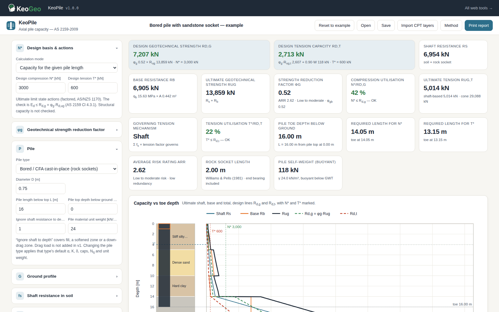
KeoPile web app — design actions, φg risk rating, pile and ground inputs on the left; design strength, utilisation and tension cards across the top; the capacity-versus-depth chart and breakdown tables update as you type.

Design actions, φg risk rating, pile and ground inputs on the left; design strength, utilisation and tension cards across the top; the capacity-versus-depth chart and breakdown tables update as you type.

What It Does

One Pile, Every Step Of AS 2159 Section 4, With The Working Shown.

KeoPile does the geotechnical part of an AS 2159 pile design the way you would on paper — layer by layer, method by method — and keeps every intermediate value on screen:

  • Design basis — Rd,g = φg·Rd,ug checked against N* (compression) and T* (tension); utilisation for both.
  • φg risk-rating calculator — the nine weighted individual risk ratings of Table 4.3.2(A), the average risk rating, the basic φgb for low or high redundancy, and the load-testing uplift φg = φgb + (φtf − φgb)·K for static, bi-directional, rapid and dynamic testing — or type φg directly.
  • Five pile types — bored/CFA cast-in-place with rock sockets, driven precast concrete (circular or square), driven steel tube (plugged, or unplugged with internal friction), steel H-section (box or actual section) and screw/helical piles with up to four helices (individual-bearing or cylindrical-shear, chosen by the S/D ≤ 3 rule or your override).
  • Layered ground — cohesive, granular and rock layers by base depth or thickness, groundwater with buoyant unit weights, an ignore-shaft depth for fill or softened zones, a pile top below ground, SPT N60 and RQD helpers, and import of a KeoCPT layers file.
  • Shaft and base in soil — α-method (constant or API 2000) and β-method (K/K0 and δ per pile type, per-layer overrides) with editable caps; Nc ramping from 6 to 9 with embedment; Berezantzev, Meyerhof, Berezantzev ÷ 3 (bored), Perko (helical) or user Nq; qb caps and a bored-pile base mobilisation factor.
  • Rock sockets — Williams & Pells, Rowe & Armitage, Kulhawy & Phoon and Horvath & Kenney shaft resistance with roughness class and mass factor j; Zhang & Einstein, Rowe & Armitage or user end bearing; warnings outside 1–100 MPa.
  • Tension — shaft resistance with tension factors versus a truncated-cone pull-out (buoyant soil and rock weight, optional surface shear, θ = φ′/2 by default), the lesser governing, plus factored buoyant pile self-weight.
  • Outputs — capacity-versus-depth chart with design lines and loads marked, required-length mode, per-layer breakdown tables, ARR table, checks, built-in verification panel, JSON save/open, autosave and an A4 print report.

Need to run many cases? KeoGeo Pro adds a CSV batch processor to this tool — A$20/month, cancel any time.

Example Outputs

What You Get Out Of It.

Design Strength Cards

Rs, Rb, Rug, φg, Rd,g and Rd,t with compression and tension utilisation, the governing tension mechanism, socket length and required lengths for N* and T*.

Capacity vs Depth Chart

Shaft, base and total ultimate resistance and the design lines against toe depth, beside the layered profile, with N* and T* marked.

Breakdown Tables

Per-layer fs and shaft resistance, base or helix bearing, the cone pull-out components and the nine-factor ARR table with φgb, K and φg.

Report And Model File

An A4 print report with every input, method and result, JSON save/open, KeoCPT layer import and a built-in verification panel.

Method & References

What The Numbers Are Based On.

Every calculation in KeoPile is tied to a published source, and the in-app Method & assumptions panel repeats this list with the defaults next to the calculations themselves:

  • AS 2159-2009 Section 4: Rd,g = φg·Rd,ug; Cl 4.3.2 risk-rating weights, basic φgb by average risk rating and redundancy, and the load-testing factors φtf and K. The table values are reproduced from secondary sources — verify against your copy of the standard.
  • Shaft resistance in soil: α-method with constant α (Skempton / Tomlinson defaults) or API RP 2A (2000); β-method with K/K0 after Kulhawy (1984) and δ after NAVFAC DM 7.2 / API; caps after API.
  • Base resistance in soil: Nc after Skempton (1951); Nq after Berezantzev et al. (1961, digitised), Meyerhof (1976) with its limiting value, Berezantzev ÷ 3 for non-displacement piles, Perko (2009) for helical plates.
  • Rock sockets: Williams & Pells (1981), Rowe & Armitage (1987), Kulhawy & Phoon (1993), Horvath & Kenney (1979); end bearing Zhang & Einstein (1998), Rowe & Armitage (1987). Mass factor j from RQD after Hobbs (1974).
  • Screw piles: individual plate bearing and cylindrical shear (Narasimha Rao et al. 1991; Perko 2009); torque correlation after Hoyt & Clemence (1989), informational only.
  • Tension: shaft resistance with uplift factors (NAVFAC DM 7.2, API) versus the truncated-cone method with θ = φ′/2 (Meyerhof & Adams 1968).
Limitations

Where It Stops, And What You Still Have To Check.

  • Single piles only: no group effects, no settlement or load-transfer analysis, no negative skin friction (down-drag) load, no structural capacity check (Cl 4.4, AS 3600 / AS 4100), no cyclic or seismic loading.
  • Empirical correlations: the digitised Berezantzev Nq and Williams & Pells β(j) curves are labelled approximations; rock-socket methods are unreliable below 1 MPa and untested above 100 MPa. Pells et al. (1998) Sydney class values are not included.
  • The AS 2159 φg tables are reproduced from secondary sources; confirm them against your copy of AS 2159-2009 before relying on them.
  • Base resistance of bored piles needs settlement to mobilise; the tool reports ultimate values only. Verify with site-specific testing and validated software before design use.

All KeoGeo tools are provided for preliminary assessment and educational purposes. Results must be verified by a suitably qualified engineer before use in design or construction; the full disclaimer is inside the app and in our terms.