Web Tools · RSW R57 External Stability Designer

RSW R57 — External Stability Of Reinforced Soil Walls To TfNSW R57.

Checks sliding, overturning, eccentricity and bearing of a reinforced soil wall for the six R57 load combinations A–F, with layered foundation soils, a high water table, strip loads behind the facing, pseudo-static earthquake pressure and undrained short-term foundation checks — and re-verifies itself against the project spreadsheet every time it opens. Free with a KeoGeo sign-in.

v1.0.0 · runs in your browser · free with an account
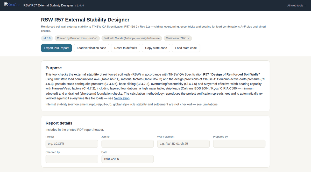
RSW R57 External Stability Designer web app — Wall geometry, surcharges, materials, foundation layers and editable design factors at the top; the results summary, wall diagram and full combination-by-combination calculation breakdown below.

Wall geometry, surcharges, materials, foundation layers and editable design factors at the top; the results summary, wall diagram and full combination-by-combination calculation breakdown below.

What It Does

Every R57 Clause, Every Load Combination, With The Working Shown.

The tool reproduces the external-stability checks of TfNSW QA Specification R57 Design of Reinforced Soil Walls (Ed 2 Rev 11), clause by clause:

  • Load combinations A–F — Table R57.1 load factors applied to the reinforced block, surcharges, traffic, strip loads and earthquake, with the governing combination reported per check.
  • Material and structure factors — Φφ, Φc (Table R57.3) with φ* = atan(Φφ·tan φ) and c* = Φc·c; structure classification factor Φn (Table R57.4); minimum reinforcement length and embedment (Tables R57.5, R57.6).
  • Earth pressures — Coulomb active wedge (Cl 4.6.3); Mononobe–Okabe pseudo-static earthquake pressure and wall inertia (Cl 4.6.6, AS 4678 App. I).
  • Strip loads — Caltrans BDS 2004, Ka·q and CIRIA C580 distributions, with the minimum adopted.
  • Sliding (Cl 4.7.3) — minimum of the base and fill interfaces plus net water resistance; passive soil resistance in front of the wall is not relied on.
  • Overturning and eccentricity (Cl 4.7.6) — moment equilibrium about the toe with the e/L limits.
  • Bearing (Cl 4.7.2) — Meyerhof effective width with Hansen/Vesic factors, up to five foundation layers, and undrained (short-term) checks.
  • Reporting — project, wall element, prepared/checked-by fields; state saves in the browser; copy-state code; PDF export.

Need to run many cases? KeoGeo Pro adds a CSV batch processor to this tool — A$20/month, cancel any time.

Example Outputs

What You Get Out Of It.

Results Summary

Utilisation or factor of safety for sliding, overturning, eccentricity and bearing under each combination, with the governing case highlighted.

Wall Diagram

Reinforced block, facing, sill beam (Type 2), foundation layers, water level and applied loads drawn to your inputs.

Calculation Breakdown

For every combination: factored properties, earth pressures, vertical load on the base, sliding, overturning about the toe and bearing — each step written out.

Verification Panel

71 spreadsheet targets compared live, with the option to load the verification inputs into the app.

Method & References

What The Numbers Are Based On.

Every calculation in RSW R57 External Stability Designer is tied to a published source, and the in-app Sources & References section repeats this list next to the calculations themselves:

  • Transport for NSW QA Specification R57 Design of Reinforced Soil Walls, Ed 2 Rev 11 (June 2020) — Cl 4.2 and Table R57.1 (load combinations), Tables R57.3–R57.6, Cl 4.6.3, 4.6.6, 4.7.2, 4.7.3 and 4.7.6.
  • Coulomb wedge theory — static active earth pressure. Mononobe–Okabe — pseudo-static earthquake pressure: θ = atan(kh/(1 − 0.5kh)), thrust × (1 − 0.5kh); AS 4678 Appendix I — inertia.
  • Meyerhof — effective-width bearing capacity; Hansen and Vesic — bearing capacity factors (Nγ).
  • Caltrans Bridge Design Specifications (2004); CIRIA C580 — strip-load distributions behind the facing.
Limitations

Where It Stops, And What You Still Have To Check.

  • External stability only. Internal stability (reinforcement rupture, pull-out, facing connections, wedge stability) must be checked by the RSW system designer.
  • Global and compound slip surfaces (R57 Cl 4.7.4) and settlement/serviceability deformations require separate slope-stability and settlement analyses.
  • Geometry scope: level or uniformly sloping crest, vertical or near-vertical facing, up to five foundation layers.
  • Some spreadsheet conventions are replicated for verification fidelity (for example how a negative water level enters certain lever arms) — the in-app limitations panel documents them.

All KeoGeo tools are provided for preliminary assessment and educational purposes. Results must be verified by a suitably qualified engineer before use in design or construction; the full disclaimer is inside the app and in our terms.